From my last electronics project, I had some leftover laser diodes. Because it would be very very sad to just have them lie around, I decided I should build something out of them. And since it’s a laser, it would be stupid to do something which doesn’t exploit the coherence properties of the light it emits, no?
Thus, I attempted to build a fourier transform spectrometer. The setup is shown below.
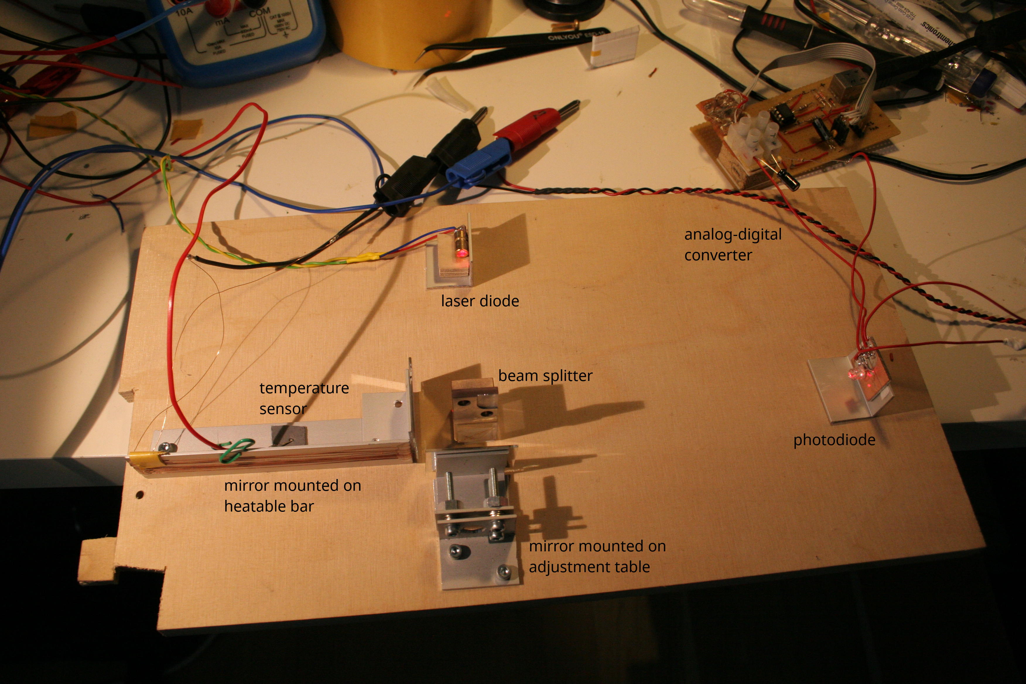
The overall setup. A Michelson interferometer is formed by the two mirrors and the beam splitter; the interference pattern is detected by a photodiode and then digitized. The heatable piece of aluminum serves as a way to move one of the mirrors in very small steps.
Concept
The general concept of a fourier transform spectrometer is that you have a Michelson interferometer, but with one arm of which the length can be changed. You then record the intensity of the output beam for different arm length differences. This intensity depends on the time delay between the two interfering beams — which can be varied by changing one of the arm lengths (i.e. moving the mirror).
The resulting “arm length vs. intensity”-curve is related to the spectrum of the analyzed light: for approximately monochromatic light, like from a laser diode, you will observe a sinusoidal pattern, because the phase relation between the two beams just changes in a linear way with the difference in path length. The “waves” formed by this pattern are called fringes (or better, interference fringes). The period of these fringes is the inverse wavelength.
Since electromagnetism is linear on this power scale, i.e. different contributions (e.g. in color) to the light field simply add up to form the final result, we can thus determine the spectrum by computing the fourier transform of the observed fringe pattern.
Realization
To build a Michelson interferometer, basically you need a beam splitter, two mirrors and a light source. For optical applications, you shouldn’t use bathroom mirrors; they have the reflective coating on the back side (instead of the front) in order to protect it. That sucks though, since there is a layer of glass between the reflective coating and the beam entry, which does all sorts of funny things (effectively, it forms a cavity and acts as a comb filter with a very fine spacing; the effect is technically the same like the colored patterns created by thin oil films, just not visible to the bare eye). Edit: While correct, this is not the point. The point is that optical mirrors have an even surface, i.e. exact to 1/8 lambda or similar over the whole area. Typical “consumer” mirrors don’t. This destroys or at least damages the interference pattern. You can buy proper mirrors, with the coating on the front side, for a few euros off ebay (search for “laser mirror” or so).
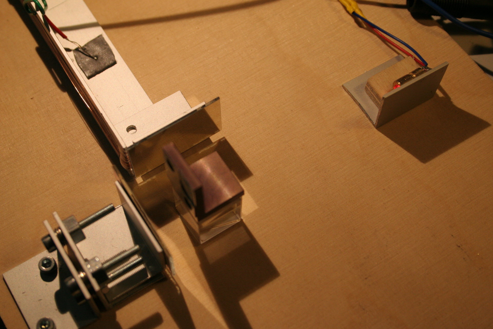
The interferometer part. The two arm lengths are relatively short, which simplifies adjustment. The laser diode is in the right of the picture.
The most expensive component you simply need to buy is the beam splitter, which is a small glass cube built to split a beam entering on one side into two halves exiting at two of its other sides: one half goes straight through, one takes a 90 degree turn. It’s hard to find those for less than $30.
You also need some kind of adjustable mount for at least one of the mirrors; a Michelson interferometer is very susceptible to misalignment. The two beams combined by the beam splitter need to have the exact same direction, or you will very quickly get to the point where no interference is observable any more (the spatial pattern spacing becomes too small to see). Sub-millirad alignment is certainly necessary to get acceptable results. For this experiment, I built an adjustment table myself from two aluminum plates, three screws and plate springs; it works okay, not a precision instrument, but what do you expect for $5.
The detector is a SFH203P photodiode simply in series with a resistor; neither speed nor sensitivity are needed for this application, so it’s trivial to build. The signal is then digitized by some USB ADC board I built years ago.
The most idiotic component of the whole setup is the variable-length arm: since it is very difficult to create a movable part with something like 100 nm resolution, I glued a mirror onto an aluminum bar and only fixed the bar on one end. By changing the temperature, the aluminum expands, shifting the mirror. For 5 cm bar length, the expansion is something like 1 µm per Kelvin. The temperature is measured by a multimeter, and recorded via USB.
Results
The actual experiment is performed by heating up the variable-length arm, then letting it cool down, recording both temperature and fringe pattern. The temperature is smoothed by fitting a model function for cooling by radiation and heat conduction to the measured values; then, the current length of the arm is computed by using the room temperature base length, and the thermal expansion coefficient of aluminum. This allows to obtain diagrams like the following for the fringe pattern versus position of the mirror:
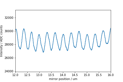
Recorded intensity on the photodiode pattern versus mirror position (computed from temperature). The recorded pattern is longer than this, this is just a small cutout.
Now, one can simply compute the fourier transform and the associated wavelengths to obtain the following spectrum with incredibly fine resolution™:
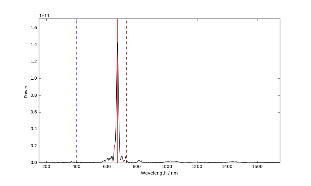
Obviously the resolution (both from the quantization and the, well, resolution point of view) is complete crap, but at least the wavelength comes out as “something in the red”, so I will call this a success. I guess the actual wavelength of the laser diode is 670 nm, and the peak is pretty close to that.
- Homemade 10 Mbit/s Laser / optical Ethernet transceiver
- Fourier Transform spectrometers vs. Grating spectrometers
Categories: Everything
so cool, especially using the heat expansion for actuation you are very clever!
hey! cool stuff
what are your thoughts on using beam splitter out of an old CD player (or optical drive)? It’s tiny (cca 5x5x5 mm) which can lead to some hard time to align but might there be some other problem?
Size sounds just fine, that shouldn’t be a problem. I think the biggest question is what the divider ratio is, because if it’s not 50:50 the interference contrast will suffer. If you try it out, let me know how it goes, sounds interesting!