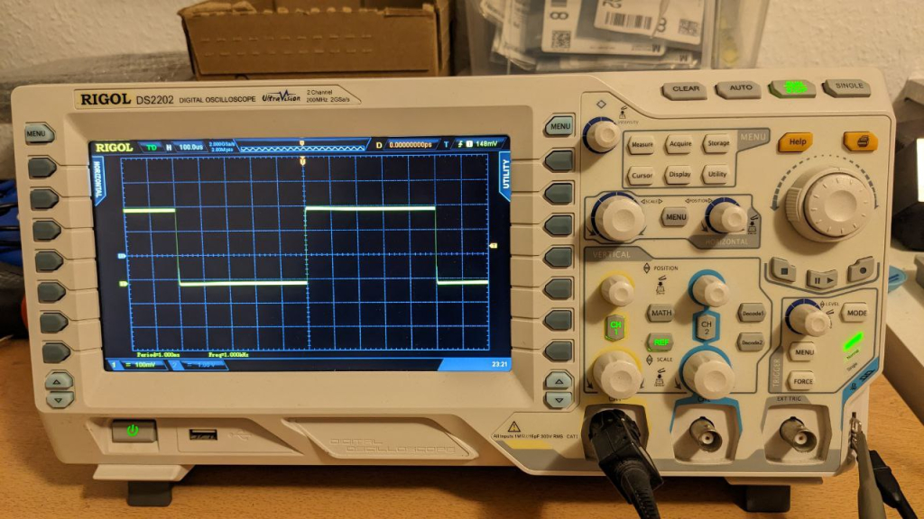
After over ten years, my Rigol DS2202 oscilloscope’s Horizontal adjustment knob unfortunately started to behave erratically, randomly zooming in and out instead of what it was supposed to do. So I decided it was in need of a replacement.
Part
This part fits pretty well: Bourns PEC11R-4115F-S0018
It also has much nicer “click” feel to it than the original part when turning, making me consider if I want to change all of them (the vertical adjustment knobs are the same).
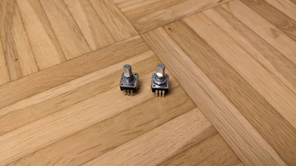
The only caveat is that the shaft is slightly (about 1.5 mm) longer than the original one, making the knob have a one-millimeter offset from the front panel. But oh well, it’s good enough.
Procedure
Doing this fix requires doing basically four things, which are fiddly to different degrees:
- Disassemble the scope to isolate the front panel board with the rotary encoder (not very fiddly)
- Remove the old rotaty encoder part (quite fiddly)
- Solder in the replacement part (trivial)
- (optional) Clean the soft buttons, while we’re at it
- Re-assemble (somewhat fiddly)
1. Disassembly
You’ll find lots of teardown videos on the internet, so I won’t go into too much detail here.
First, pull off all the rotary knobs from the front panel. They are just clipped on, so there’s nothing to do except pulling.
Then, remove the dark grey back cover. Two of the screws are hidden behind the handle.
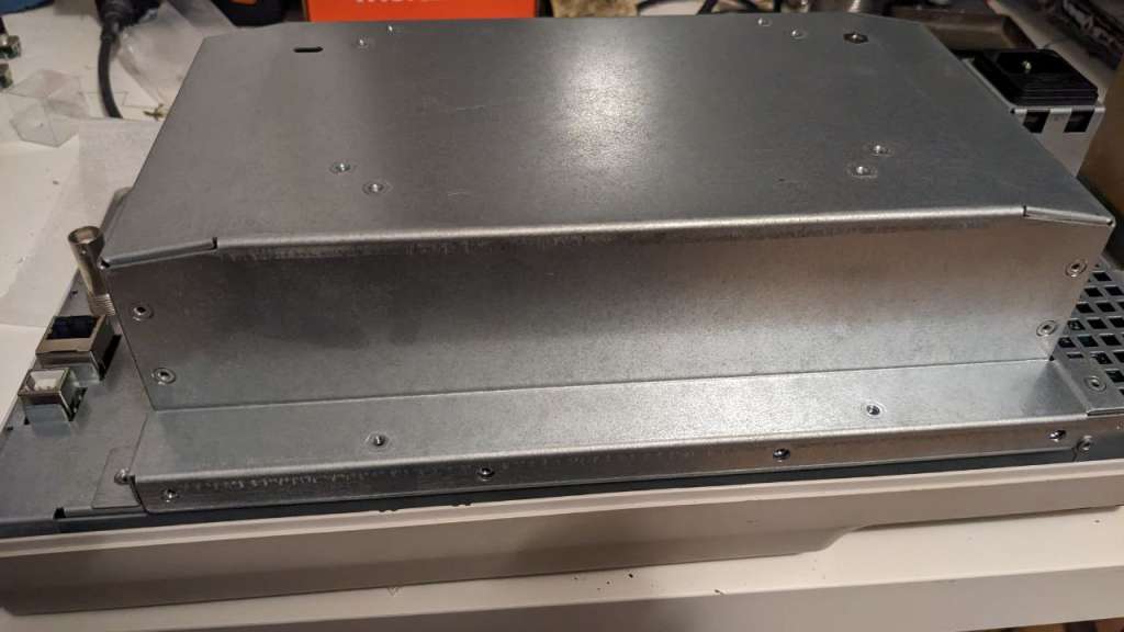
Next, remove the power supply. This requires removing some screws, then lifting it off a bit, unplugging two cables, then removing it completely.
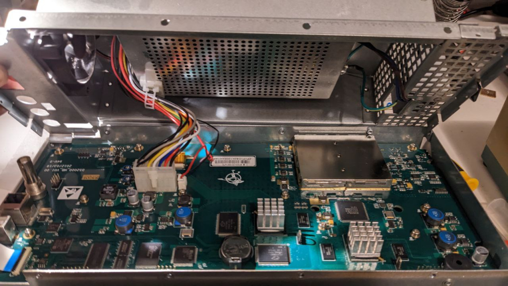
The bigger wire is fixed quite firmly, it requires some force to pull off. (Don’t forget to push the pin, of course.)
Next, remove the screws next to / below (not the ones on top of!) the big PCB. Also remove the white flex cable by lifting up the black tab on the connector and pulling it out. You don’t need to remove the (brown) screen’s flex cable going through the PCB.
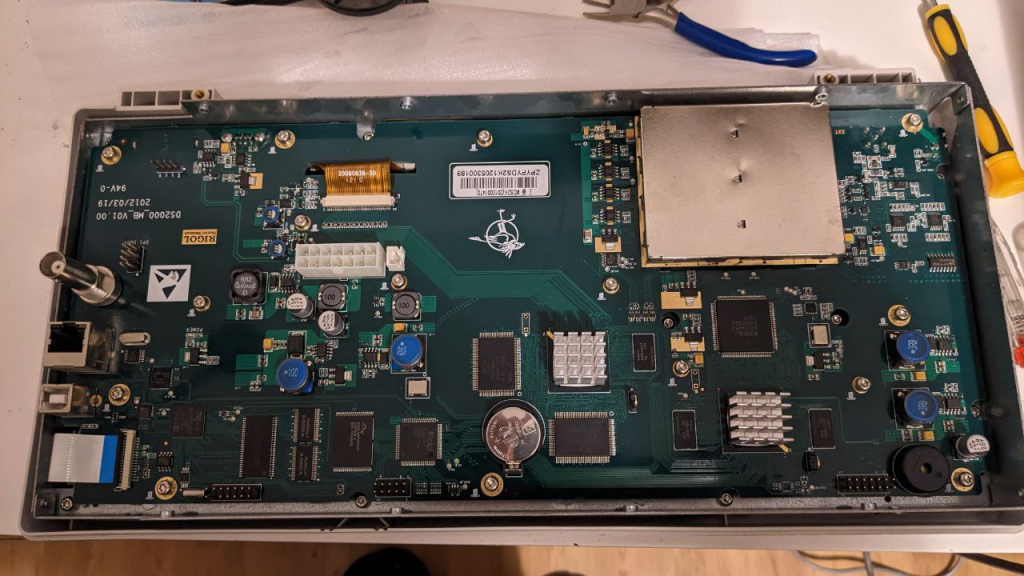
Grab the whole metal frame holding the main PCB and lift it off. Flip it around.
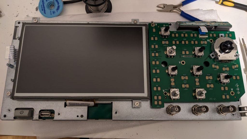
Unscrew the screws holding the right front panel PCB in place. Disconnect the small white flex wire connecting to the Clear/Run/Single buttons on the top right. Unscrew the screws holding the narrow left front panel PCB in place (removed already in the picture). Disconnect the white flex cable from the narrow left PCB. Carefully remove the right front panel PCB with the white flex cable by dragging it to the right.
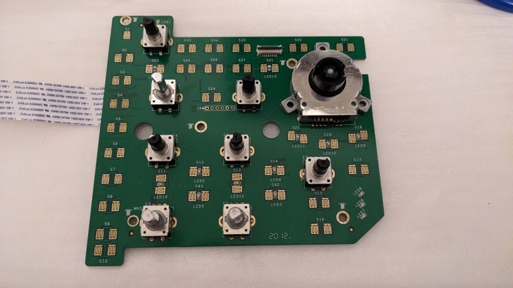
There we have it!
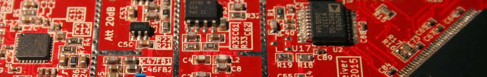
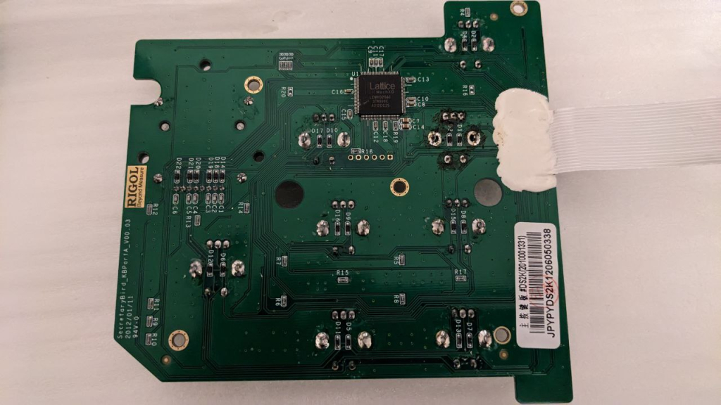
2. Remove the old rotary encoder
This is the most difficult part of this repair. I think I made it a bit more difficult by trying to keep the old part intact. If I had to do it again, with the confidence that my replacement part actually fits and works, I think I would just use a wire cutter to cut of the pins of the broken part, and de-solder them individually. Getting it out in one piece is a bit more hassle.
First, you need a high-power soldering iron, or this is not going to work.
Then what I did was to de-solder the five small pins of the part completely such that they are loose; this works well with some solder wick. Now only the two big ground pins remain. I added some solder to the tip of my iron and put it onto one of the pins, waited until all the solder had melted, and pressed lightly. This tilts the part just a little bit, pushing one of the pins out by a millimeter or so. By alternatingly repeating this with both pins, after 5-6 iterations it will fall out.
The important thing with this technique is to be very careful with how much force you apply (you need very little), and waiting until the solder has actually all melted. Otherwise you risk ripping the pads off the PCB.
3. Soldering in the new rotary encoder
This is the easiest part, really nothing to say here. Just clean the holes with some solder wick, the new part should fit right in, then just solder it on. Make sure it’s fully flush with the PCB.
4. (optional) Clean the soft buttons, while we’re at it
Some of my soft buttons, especially Run/Stop and Single, had also become somewhat jerky and sometimes wouldn’t react. Rubbing them with a soft tissue paper drenched with isopropyl alcohol, then wiping them dry with a fresh paper resolved this problem. It’s a pretty free maintenance thing to do when everything is disassembled anyways.
5. Re-assembly
This basically works like the disassembly, but in reverse. One thing which cost me a bit of nerve is that the Clear/Run/Single button assembly is held in place by a small plastic cage. This cage needs to click into the main assembly, which is not something that happens automatically when just putting it on top of the front panel plastic and tightening the screws. You need to do it manually as the first step, and only then put the main assembly back onto the front cover.
Before tightening the screws, make sure to check your front panel for any eventually misaligned soft button foil.
The second-hardest part was getting the white flex cable of the front panel back under the screen, but with a bit of patience and wiggling this is quite doable. The rest is uneventful.
And there we are, as good as new! The 1mm offset from the different knob length is more of a cosmetic issue and I’d guess most people wouldn’t notice unless specifically told about it.
- Rotate/Pan/Zoom camera navigation in QOpenGLWidget
- Fourier Transform Spectroscopy continued, or: How to reproduce NIST ASD results to 8+ digits at home
Categories: Everything